Final CAD
Design for Exoskeleton Leg Support in Fusion 360
Project Overview
Objective:Design a piece in Fusion 360 to hold a leg using Velcro straps, connected to a 2020 aluminum profile, with designated spaces for an IMU sensor and mounting brackets for a linear actuator.
Components and Materials
2020 Aluminum Profile:
- Standard aluminum extrusion used for the main structural frame.
- Provides strength and stability to the exoskeleton.
Velcro Straps:
- Used to secure the leg to the structure.
- Adjustable and comfortable for the user.
IMU Sensor Mount:
- A specific holder designed to securely place the IMU sensor.
- Ensures accurate tracking of leg movements.
Mounting Brackets:
- Custom brackets to attach and hold the linear actuator.
- Designed to provide the necessary range of motion and support.
Linear Actuator:
- Mechanism to provide mechanical support and assistance.
- Mounted on the brackets and connected to the structure.
Design Process
Step 1: Setting Up the Fusion 360 Workspace
- Open Fusion 360 and create a new project.
- Set up the units (millimeters are recommended for this project).
- Import or draw the 2020 aluminum profile as the base structure.
Step 2: Designing the Velcro Strap Holder
- Create a sketch on the appropriate plane where the Velcro strap will be mounted.
- Design a rectangular cutout or slot that fits the Velcro strap width.
- Add fillets to the edges for smoothness and comfort.
- Extrude the sketch to create a 3D part that can be attached to the aluminum profile.
Step 3: Creating the IMU Sensor Mount
- Identify the placement of the IMU sensor on the structure.
- Sketch a holder or bracket that fits the dimensions of the IMU sensor.
- Include mounting holes or clips to securely attach the sensor.
- Extrude and finalize the shape, ensuring it aligns correctly with the aluminum profile.
Step 4: Designing the Linear Actuator Mounting Brackets
- Determine the mounting points on the aluminum profile for the actuator.
- Sketch the bracket design, considering the actuator’s dimensions and range of motion.
- Include holes or slots for screws and bolts to attach the actuator.
- Extrude the bracket and ensure it fits snugly on the profile.
Step 5: Assembly
- Assemble all the designed parts in Fusion 360.
- Use joints and constraints to simulate real-world movement and ensure all parts fit together correctly.
- Check for any interference or misalignment.
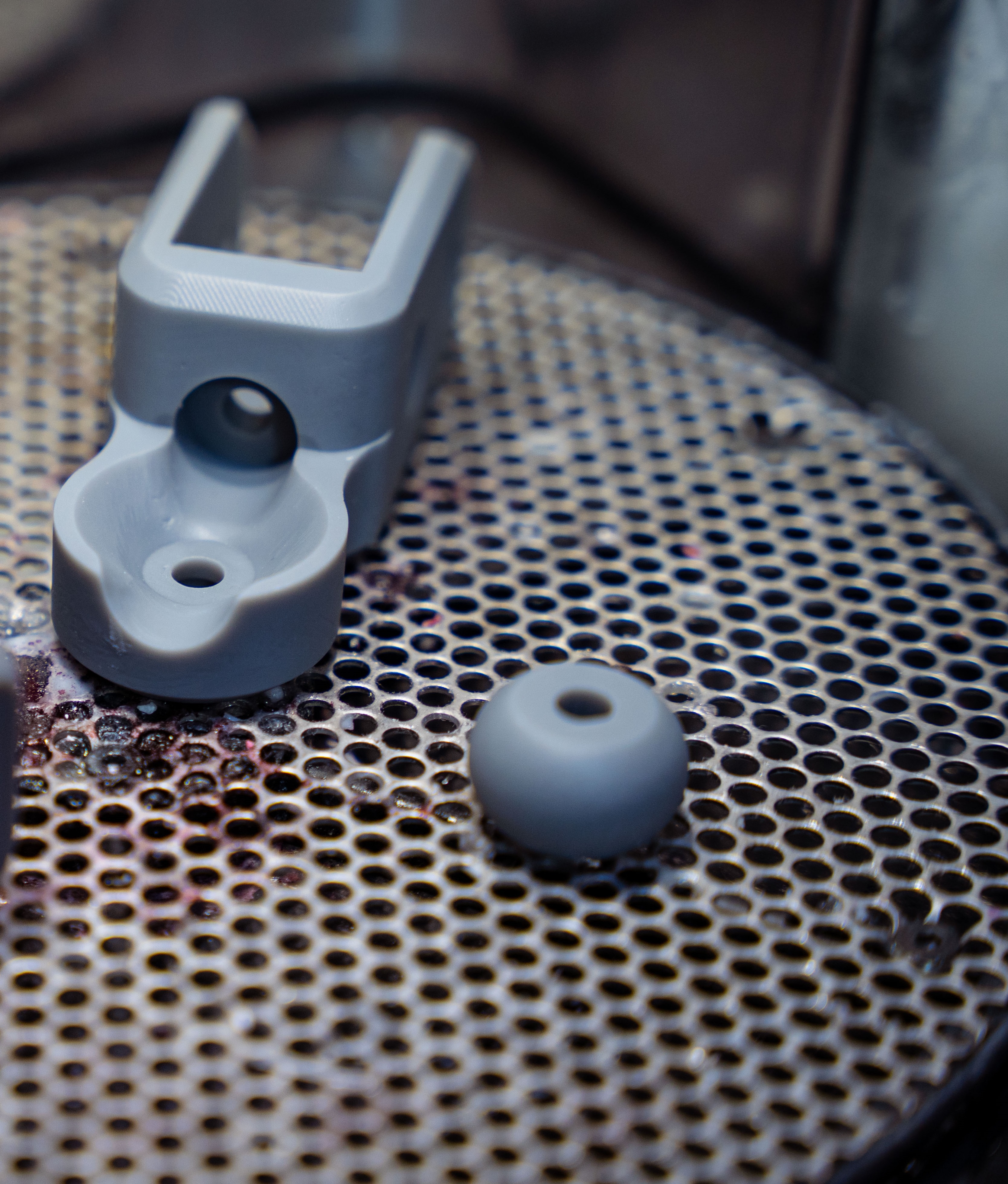
3D Printing Documentation: Using Cura Slicer with Ultimaker S5
Project Overview
Objective: To design and print 3D components for the exoskeleton project using Cura slicer and Ultimaker S5 3D printer.
Tools and Materials
- Cura Slicer:
- Software used for preparing 3D models for printing.
- Ultimaker S5:
- A high-quality 3D printer used for creating the physical parts.
- 3D Design Files:
- STL or OBJ files created or downloaded for the project.
- Filament:
- PLA, ABS, or other materials compatible with the Ultimaker S5.
Design Process
Step 1: Creating 3D Models
- Design Software:
- Use any 3D design software like Fusion 360, Tinkercad, or Blender to create your models.
- Save your design as an STL or OBJ file.
Step 2: Preparing the Model in Cura
Open Cura:
- Launch Cura on your computer.
Import the Model:
- Click on “Open File” and import your STL or OBJ file into Cura.
Position the Model:
- Use the move, scale, and rotate tools to position your model on the build plate.
- Ensure the model fits within the build volume of the Ultimaker S5.
Select the Printer:
- Choose the Ultimaker S5 from the list of available printers in Cura.
Adjust Print Settings:
- Choose the appropriate material profile (e.g., PLA, ABS).
- Set the layer height, infill density, print speed, and support structures as needed.
- Use predefined profiles for ease or customize settings for specific needs.
Slice the Model:
- Click on “Slice” to generate the G-code file.
- Review the estimated print time and material usage.
Save the G-code:
- Save the G-code file to a USB drive or send it directly to the Ultimaker S5 if connected.
Step 3: Printing the Model on Ultimaker S5
Prepare the Printer:
- Turn on the Ultimaker S5.
- Ensure the build plate is clean and level.
- Load the filament into the printer.
Load the G-code File:
- Insert the USB drive into the printer or access the file over the network.
- Select the file from the printer’s interface.
Start the Print:
- Confirm the print settings and start the print job.
- Monitor the first few layers to ensure proper adhesion and check for any issues.
Printing Process:
- Allow the printer to complete the job.
- Monitor periodically to ensure everything runs smoothly.
Remove the Print:
- Once the print is complete and cooled, carefully remove it from the build plate.
- Use tools like a spatula if necessary to assist in removal.
Final Review and Post-Processing
Inspect the Print:
- Check the printed part for any defects or issues.
- Ensure it meets the required dimensions and quality.
Post-Processing:
- Remove any support structures.
- Sand or trim edges if necessary.
- Assemble the printed parts with other components of your project.
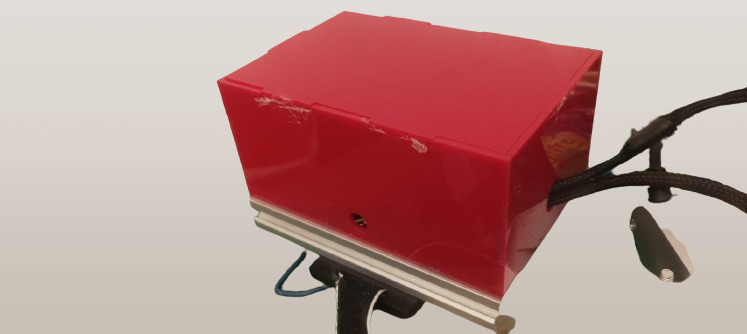
Making a Cool Box for My Exoskeleton's Electronics
What's the Plan?
I needed a neat way to hide and protect the electronic bits of my exoskeleton. So, I decided to make a custom box using a laser cutter. Here's how I did it, step by step.
Tools and Materials
Trotec Speedy 400 Laser Cutter:
- This is the magic machine that cuts and engraves stuff with precision.
Makercase Website:
- An online tool that helps create box designs.
Inkscape:
- A program for editing and tweaking the design.
Material:
- I used acrylic or plywood sheets, perfect for laser cutting.
Step-by-Step Process
Step 1: Designing the Box on Makercase
Go to Makercase:
- Head over to Makercase.
Set Box Dimensions:
- Enter the size you want for the box (length, width, height).
- Choose the joint type (finger joints work great for this).
Set Material Thickness:
- Input how thick your material is (e.g., 3mm or 6mm).
Generate the Design:
- Click “Generate Laser Cutter Case Plans” and download the SVG file.
Step 2: Tweaking the Design in Inkscape
Open Inkscape:
- Fire up Inkscape on your computer.
Import the SVG File:
- Open the SVG file you got from Makercase in Inkscape.
Edit Away:
- Adjust the design to fit your needs.
- Add holes for cables, ventilation, and mounting spots for the electronics.
- Add any labels or engravings you want.
Save Your Design:
- Save the updated design as an SVG file.
Step 3: Getting Ready for Laser Cutting
Prep Your Material:
- Place the acrylic or plywood sheet on the laser cutter bed.
Set Up the Laser Cutter:
- Configure the laser cutter settings based on your material.
Step 4: Laser Cutting Time
Start Cutting:
- Begin the cutting process and keep an eye on it to make sure everything goes smoothly.
Collect Your Pieces:
- Carefully take out the cut pieces from the laser cutter.
Step 5: Putting It All Together
Test Fit:
- Check if the pieces fit together properly.
Assemble the Box:
- Use glue or another adhesive to assemble the box.
- Make sure all the joints are secure.
Install the Electronics:
- Place your electronic components inside the box.
- Secure them with screws, standoffs, or Velcro.
- Route the cables through the cutouts and ensure good ventilation.
.svg)